Diagnostic monitor calibration for techs
Standards-first, technician-ready diagnostic monitor calibration aligned to DICOM GSDF and AAPM Report 270. Acceptance, monthly, and annual steps
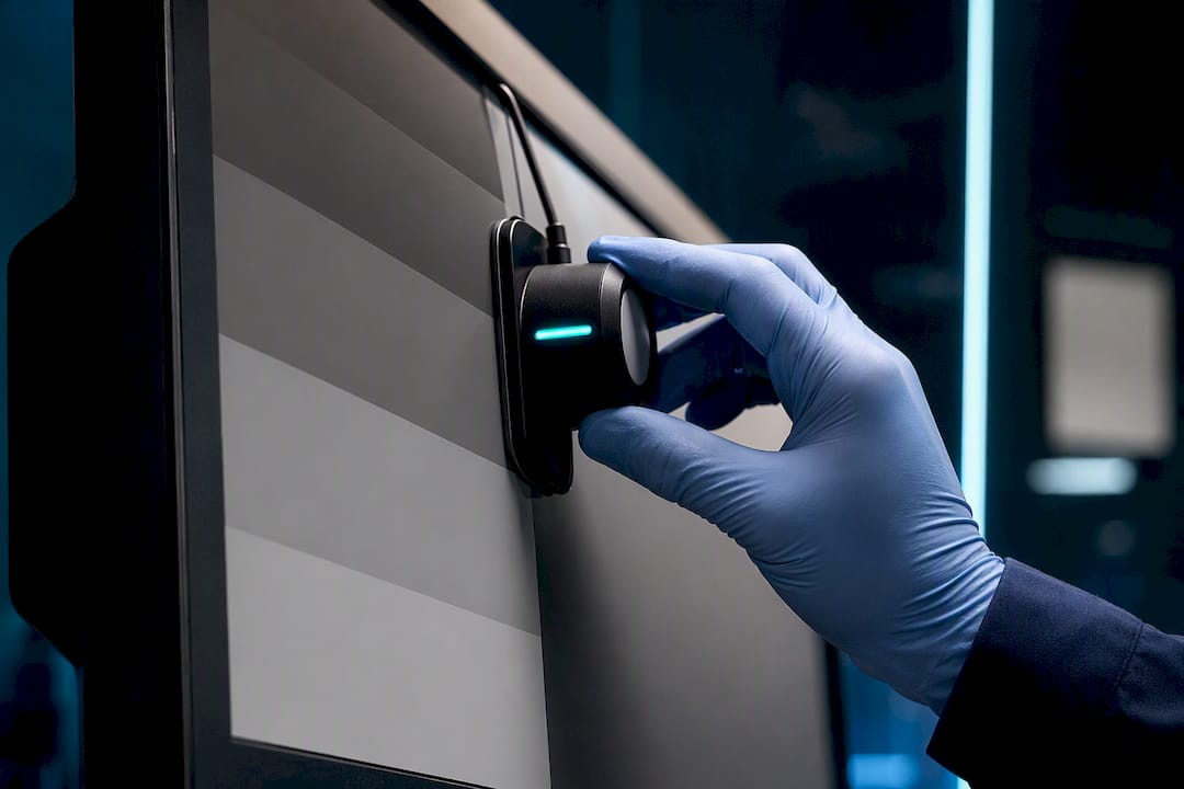
Diagnostic monitor calibration brings a display's grayscale response into conformance with the DICOM Grayscale Standard Display Function and your site's QA tolerances. If you're not sure where your displays currently stand, the immediate move is a TG18 or SMPTE pattern check with a calibrated external photometer. A glance at the vendor's on-screen indicator does not count. Anchor the process to DICOM GSDF and AAPM TG-270, and treat everything else as implementation detail.
AstraRad has a commercial interest in this topic and it is worth saying so. Our board-certified subspecialists read studies that arrive from facilities' own workstations, and the turnaround commitments we publish assume the images were rendered inside GSDF tolerance on the sending side. A referring site's drifted display is one failure the reading radiologist cannot see, which is why the checklist below matters to a remote reader as much as to the local technologist.
TL;DR:
- Most internal sensors drift over time, so regular external cross-calibration with traceable photometers is essential for accurate QA results.
- Ambient light levels in reading rooms should be maintained between 25 and 75 lux to prevent glare that can mask low-contrast details on calibrated displays.
- Automated QA systems must include escalation pathways to ensure flagged issues are reviewed by qualified personnel instead of dismissed without action.
- Display luminance should stay within 400 to 600 cd/m² for monochrome diagnostic displays, with deviations kept under 10% for primary monitors.
- Calibration logs should be integrated into PACS or radiology IT systems to enable real-time monitoring and prevent reading on non-compliant displays.
Table of Contents
- Diagnostic Monitor Calibration Checklist: What to Do Right Now
- What Are DICOM GSDF Targets and JND Tolerances?
- Which Tools Measure and Correct Diagnostic Displays?
- How Do You Build a Full Calibration and QC Workflow?
- What Pass/Fail Criteria Confirm a Successful Calibration?
- Why Do Calibrated Displays Still Fail QA?
- Sample QC Schedule and Log Fields for Diagnostic Displays
- How Does Calibration Data Connect to PACS and Radiology IT?
- Why Display QA Matters for Remote Radiology Reads
- Key Standards and Tools for Diagnostic Display QA
- Display QA for Remote Reading
- Sources
Diagnostic Monitor Calibration Checklist: What to Do Right Now
Before you touch a measurement device, get the environment right. A miscalibrated room produces a "failed" reading on a perfectly good display, and vice versa.
- Warm up the display for at least 20 to 30 minutes, clean the panel, and measure ambient light with a lux meter at the reading position.
- Run TG18 or SMPTE test patterns and visually confirm the 5% and 95% patches, plus the low-contrast resolution targets.
- Measure luminance with a calibrated external photometer, or with a validated internal sensor that's been cross-checked against an external device.
- Log the display ID, model, hours in service, measured Lmin/Lmax, GSDF deviation, and the technologist who ran the test.
Skip step 3's cross-check and you risk trusting a sensor that's already drifted, which is a bigger problem than most QA programs admit.
What Are DICOM GSDF Targets and JND Tolerances?
The GSDF maps digital driving levels (DDL) to displayed luminance using perceptual units called just noticeable differences, or JNDs. Instead of a simple linear ramp, the function accounts for how the human eye perceives contrast differently at low and high luminance, which is why a raw gamma curve fails clinical review even when it looks fine on a spreadsheet.
Historical guidance points to these working ranges:
- Monochrome primary diagnostic displays: Lmax around 400 to 600 cd/m²
- Color clinical-review displays: Lmax around 250 to 450 cd/m²
- Recommended luminance ratio (Lmax divided by Lmin): roughly 300 to 400
GSDF deviation tolerance: most QA programs hold primary diagnostic displays to a maximum 10% deviation from the ideal GSDF curve, and allow up to 20% for clinical-review displays, per AAPM Report 270 guidance. An 8-bit display has 256 DDLs, so building a lookup table means dividing total JNDs across the Lmin to Lmax range by 255 to get JND-per-DDL, then mapping input to output accordingly.
Which Tools Measure and Correct Diagnostic Displays?
Front-of-screen contact photometers remain the reference standard because they measure light exactly where a radiologist's eye receives it, provided the sensor is baffled to exclude ambient reflection. Telescopic photometers work from a distance and suit large-format or curved displays where contact placement is awkward.
- Contact photometers: highest accuracy for routine QC, require NIST-traceable calibration certificates.
- Telescopic photometers: useful for displays you can't physically touch, slightly more setup time.
- Colorimeters: add value for color modalities like digital pathology or dermatology imaging, where hue and saturation accuracy matters as much as luminance.
- Internal (built-in) sensors: convenient for automated, unattended QA, but documented to drift over time.
Software applies corrections through an 8-bit to 8-bit lookup table, adjusting each DDL's output so the measured curve tracks the GSDF target instead of a native linear response, as described in the DICOM grayscale calibration literature.
Pro Tip: Never rely on a display's internal sensor alone for compliance reporting. Cross-check it against a traceable external photometer at least quarterly, or right after any firmware update, and treat any gap over 10% as a trigger for recalibration.
How Do You Build a Full Calibration and QC Workflow?
A defensible QA program has four layers, each with a different owner and a different frequency. Skipping the acceptance step is the most common shortcut, and it's the one that causes headaches two years later when nobody has a baseline to compare against.
- Acceptance testing. Performed at install or after relocation, ideally by a medical physicist. This establishes baseline luminance, uniformity, and confirms the display meets vendor specifications before it ever reads a study.
- Monthly routine QC. A technologist runs TG18 or SMPTE quick checks, typically taking a few minutes per display, confirming contrast blocks, inspecting for artifacts, and logging results, following guidance in primary display QC protocols.
- Annual quantitative review. A physicist or qualified specialist performs a full luminance sweep across all DDLs, verifies GSDF conformance, and checks uniformity and color metrics on affected modalities.
- Automated QA integration. Where volume justifies it, automated systems can run scheduled checks across dozens or hundreds of displays with full security and HIPAA compliance. Define a cross-calibration interval for any internal sensor feeding that system, and set alarm thresholds that escalate to a technologist or physicist when deviation exceeds your tolerance, well before the display outright fails.
The fourth layer only works if someone owns the escalation path. An automated system that flags a problem nobody reviews is worse than no automation at all.
What Pass/Fail Criteria Confirm a Successful Calibration?
TG18 and SMPTE patterns give you the visual confirmation layer: the 5% and 95% patches should be distinguishable from their neighbors, and low-contrast resolution targets should remain visible without gaps.
- Primary diagnostic displays: GSDF deviation should stay at or below 10%
- Clinical-review displays: GSDF deviation tolerance extends to 20%
- Luminance ratio: target the 300 to 400 range for most diagnostic panels
- Ambient light: keep reading rooms in the range of roughly 25 to 75 lux to avoid glare washing out low-contrast detail
A useful benchmark: a recent automated QA rollout across 53 diagnostic displays found that only 9% initially met updated GSDF tolerances, rising to 68% after internal sensors were recalibrated against a traceable external reference. That gap is the entire argument for cross-calibration, in one statistic.
Uniformity checks matter too: luminance should not vary meaningfully from center to edge of the panel, since an uneven backlight can pass a center-point spot check while still degrading edge-of-field diagnostic detail.
Why Do Calibrated Displays Still Fail QA?
Most calibration failures trace back to four repeat offenders, and none of them require a new display to fix.
- Internal sensor drift. The same automated QA study found 53% of internal photometers showed more than 10% error against a traceable external unit. Cross-calibrate on a defined schedule, and replace the sensor if drift keeps recurring.
- Backlight aging. LED backlights lose brightness over years of use. When a display can no longer reach its target Lmax without excessive gain, reduce the target or plan for replacement, and stop pushing the panel past its usable range.
- Ambient light misconfiguration. Reflections and glare wash out low-contrast detail even on a perfectly calibrated panel. Remeasure lux at eye level instead of at the wall switch.
- Measurement technique errors. Edge measurements instead of center-of-screen, unbaffled sensors picking up stray light, and rushed warm-up periods all produce misleading readings.
Pro Tip: If a display fails QC right after a "clean bill of health" from its internal sensor, suspect the sensor first, not the panel. That mismatch is exactly the pattern recent field data flagged.
Sample QC Schedule and Log Fields for Diagnostic Displays
A workable QA program assigns monthly checks to technologists and annual quantitative work to a medical physicist, then tracks the results in a shared log.
| Frequency | Task | Performed by | Key fields logged |
|---|---|---|---|
| Monthly | TG18/SMPTE visual check | Technologist | Display ID, contrast pass/fail, artifacts noted |
| Quarterly | Internal sensor cross-calibration | Technologist or physicist | Sensor deviation %, action taken |
| Annual | Full luminance sweep, GSDF conformance | Medical physicist | Lmin, Lmax, luminance ratio, GSDF deviation %, uniformity |
Trend data across these logs tells you more than any single reading. A display drifting steadily toward its Lmax ceiling over 18 months is telling you to budget for replacement before it fails outright during a busy reading shift.
How Does Calibration Data Connect to PACS and Radiology IT?
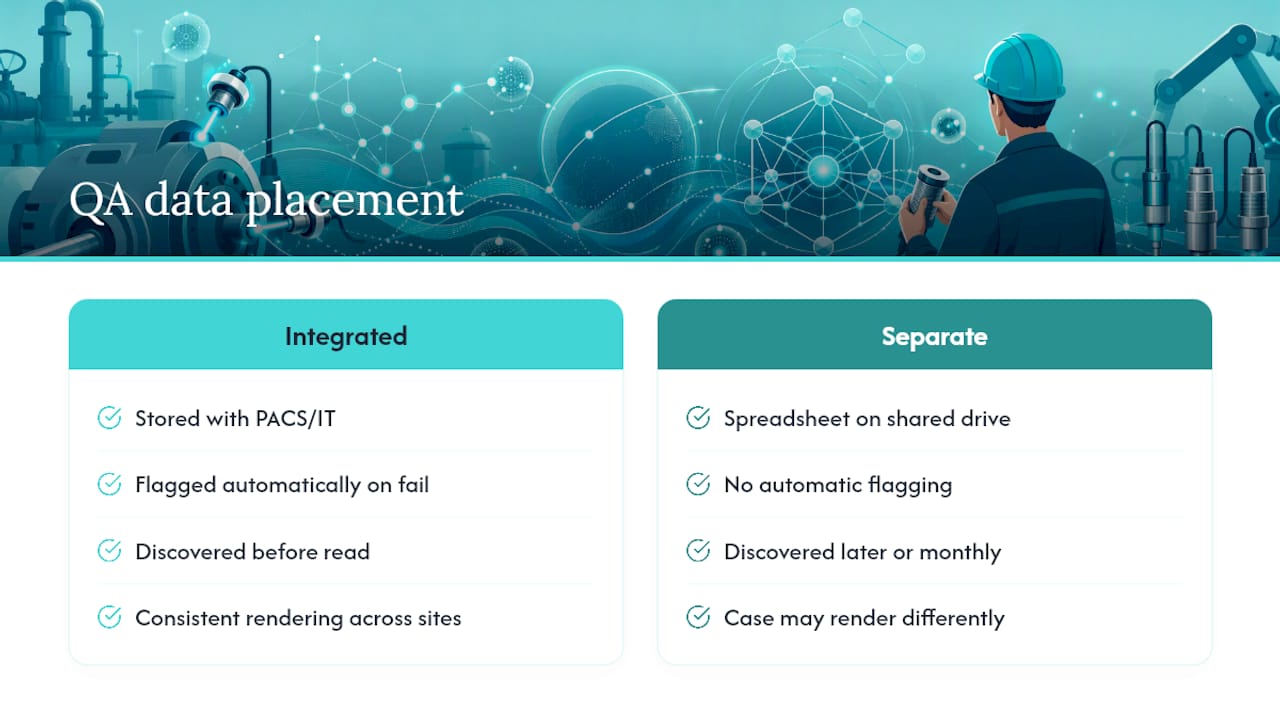
Calibration results only create lasting value when they live somewhere besides a spreadsheet on a shared drive. Most enterprise imaging environments now route QA logs into the same infrastructure that manages studies themselves, tagging each display's calibration status against its unique device identifier so a failed or overdue check can be flagged before a radiologist opens a study on that workstation.
That matters most in distributed reading environments, where physicians review studies across multiple sites or from remote workstations. If one site's displays run out of GSDF tolerance while another's stay compliant, the same case can present differently depending on which monitor renders it, undermining consistency in ways a radiologist may never suspect during a routine read. Enterprise deployments have used automated, remotely monitored QC systems to scale this kind of tracking across hundreds of workstations, but the underlying principle holds at any scale: calibration status should be queryable alongside the imaging data it protects instead of filed separately.
Integrating QA metadata into your radiology IT stack, whether through a PACS module, a dedicated QA management platform, or an HL7/FHIR feed, means a failed display gets flagged automatically instead of discovered after a misread. That's a meaningfully different failure mode than catching it on next month's manual check.
Why Display QA Matters for Remote Radiology Reads
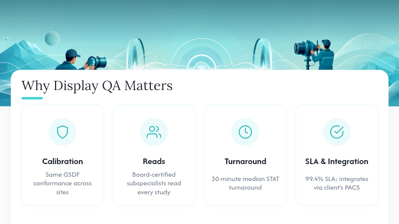
Consistent calibration across sites keeps a study looking the same whether it's read locally or by a remote subspecialist, which matters enormously once interpretation crosses institutional boundaries. A reading group's turnaround commitment is only as good as the display the study was rendered on: a subspecialist signing within the hour assumes the images meet the same GSDF conformance the local radiologist expects. When the reads flow through the client's existing PACS workflow with no separate portal, display QA on the sending side is the one link in that chain nobody on the reading side can inspect.
Key Standards and Tools for Diagnostic Display QA
- AAPM Report 270: the reference framework for standards-based display QA and automated testing.
- DICOM Part 14 / GSDF via SIIM: the grayscale standard itself, explained with practical calibration context.
- Grayscale calibration and LUT methodology: the mechanics of building an 8-bit lookup table from JND data.
- Automated QA implementation study: field evidence on internal sensor drift and recalibration outcomes.
Display QA for Remote Reading
Radiology groups often treat display calibration as a local IT checkbox, disconnected from reading quality. That's backwards. A subspecialist reading a chest CT at 2 a.m. depends entirely on the referring site's display rendering that study within GSDF tolerance, because no radiologist can compensate for a monitor quietly running 15% out of spec.
Where this gets practical for distributed reading networks: QA status needs to travel with the study instead of sitting in a binder at the imaging center. Groups evaluating remote coverage should ask any provider how display QA integrates with their existing PACS before signing anything.
This article is general information, not a substitute for advice from a qualified doctor. Consult a qualified healthcare professional about your own circumstances before acting on anything here.
Recommended
Related on AstraRad
- Resources
2027 Medicare fee schedule: the radiology numbers explained
The CY2027 Medicare fee schedule cuts both conversion factors while ACR estimates radiology gains 2 percent. Both are true. Model your dollars per RVU.
- Resources
Clinician-radiologist communication: closing the loop
Clinician-radiologist communication fails when critical results reach a system but never reach the physician, and closed-loop standards close that gap.
- Resources
The hidden cost of the prelim-plus-overread model
The prelim-plus-overread model pays two radiologists and bills one report per overnight study. Cost the overread time, callbacks, and amendments first.
Put a radiologist's name on your next read.
Tell us your modalities and monthly volume. A complete per-report rate card, with turnaround tiers and SLA terms in writing, lands in your inbox within one business day.